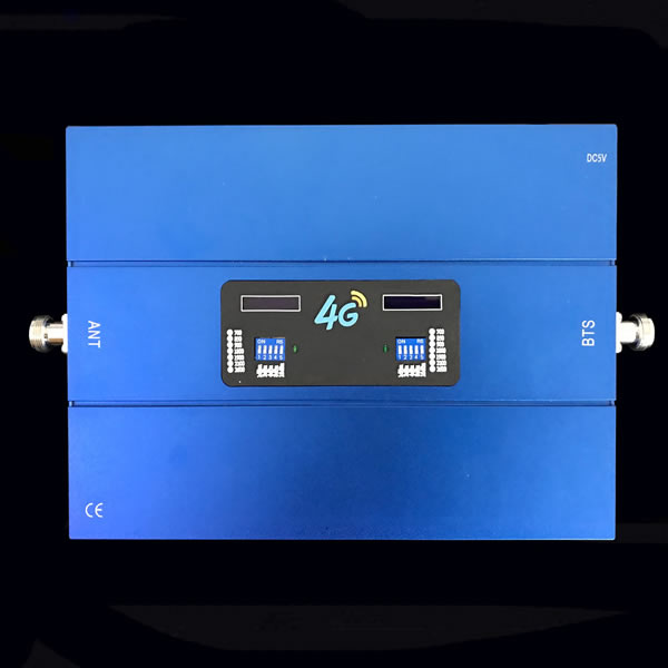
GSM900 DCS1800 Dual band signal booster Coverage 2500m2
GSM900 DCS1800 Dual band signal booster Coverage 2500m2
Description
There are millions of very small areas (10~2500 square meters) where people work or live in and suffer from very poor or no mobile signals. People are seeking a cheap and immediate solution that would allow them have clear phone calls or higher speed broad band. However most of the current repeater solutions usually have larger coverage size, which is cost effective. ST-GD-27A is specifically designed as a "CHEAP" solution to meet this request.
1. The consumer repeater is an ideal solution for providing a costeffective improvement in cellular in-building coverage of a home, office, restaurant or building, in the quickest time possible.
2. Manual gain control (MGC total 31dB range with all DIP switches for each link) available for both uplink and downlink to adjust the gain value for proper coverage during installation or maintenance.
3. To maintain safe and specific output signal levels and give alarms on self-oscillation, the repeater has built-in AGC and ALC circuits, which can automatically control the gain of the repeater depending upon the strength of input signals.
4. Auto shut off function available for both uplink and downlink to avoid deep self-oscilation from jamming the towers, saving your trouble from operators.
5. It supports two systems of GSM900 and DCS1800mhz.
HPC LCD Dual band repeater Features:
1. With unique appearance design, have good cooling function
2. With MGC function,(Manual Gain Control), Customer can adjust the Gain as needed ;
3. With DL signal LED display, help to install the outdoor antenna at the best state;
4.With AGC and ALC, make repeater work stable .
5.PCB with isolation function ,make UL and DL signal not influence each other,
6.Low intermodulation, high Gain ,stable Output power
7. With LCD signal display , Help to know the repeater working performance correctly
HPC LCD Dual band repeater Design

Specification of HPC LCD Dual band repeater:
|
Electrical specification |
Uplink |
Downlink |
||
|
Frequency Range |
GSM900 & EGSM + WCDMA/3G2100mhz |
880-915 MHz
1920-1980 MHz |
925-960 MHz
2110-2170 MHz |
|
|
GSM900EGSM+DCS/LTE1800mhz
GSM900 +LTE 800 |
880-915 MHz
1710-1785 MHz |
925-960 MHz
1805-1880 MHz |
||
|
DCS/LTE1800+WCDMA 2100mhz |
1710-1785 MHz 1920-1980 MHz |
1805-1880 MHz
2110-2170 MHz |
||
|
CDMA850+PCS1900mhz |
824-849mhz
1850-1910 MHz |
869-894mhz
1930-1990 MHz |
||
|
LTE2600+WCDMA 2100mhz |
1920-1980 MHz
2500-2570MHz |
2110-2170 MHz
2620-2690MHz |
||
|
CDMA850 +3G 2100mhz |
824-849mhz
1920-1980 MHz |
869-894mhz
2110-2170 MHz |
||
|
DCS/LTE1800+4G LTE 2600mhz |
1710-1785 MHz 2500-2570 MHz |
1805-1880 MHz
2620-2690 MHz |
||
|
Max .Gain |
≥ 72dB |
≥ 75dB |
||
|
Max .Output Power |
≥ 24dBm |
≥ 27dBm |
||
|
MGC ( Step Attenuation ) |
≥ 31dB / 1dB step |
|||
|
Automatic Level Control |
≥ 20dB |
|||
|
Gain Flatness |
GSM & CDMA |
Tpy≤ 6dB(P-P); DCS,PCS ≤ 8dB(P-P) |
||
|
WCDMA |
≤ 2dB/ 3.84MHz,Full Band ≤ 5dB(P-P) |
|||
|
Noise Figure |
≤ 5dB |
|||
|
VSWR |
≤ 2.0 |
|||
|
Group Delay |
≤ 1.5μs |
|||
|
Frequency stability |
≤ 0.01ppm |
|||
|
Spurious Emission & |
GSM Meet ETSI TS 151 026 V 6.1.0 |
|||
|
WCDMA Meet 3GPP TS 25.143 ( V 6.2.0 ) |
||||
|
CDMA Meet IS95 & CDMA2000 |
||||
|
WCDMA System |
Spurious Emission Mask |
Meet 3GPP TS 25.143 ( V 6.2.0 ) |
||
|
Modulation Accuracy |
≤ 12.5% |
|||
|
Peak Code Domain Error |
≤ -35dB@Spreading Factor 256 |
|||
|
CDMA System |
Rho |
ρ > 0.980 |
||
|
ACPR |
Meet IS95 & CDMA2000 |
|||
|
Mechanical Specifications |
Standard |
|||
|
I /O Port |
N-Female |
|||
|
Impedance |
50 ohm |
|||
|
Operating Temperature |
-25ºC~+55ºC |
|||
|
Environment Conditions |
IP40 |
|||
|
Dimensions |
220x320x40mm |
|||
|
Weight |
≤ 2.00Kg |
|||
|
Power Supply |
Input AC90-264V,output DC 5V / 6A |
|||
|
LED Alarm |
Standard |
|||
|
Uplink signal LED |
Be lighted when there is phone calling |
|||
|
LCD Display |
Power supply LCD lighted |
|||
LED Display Introduction :


The installtion of the Repeater
Outdoor antenna ( for receiving the signal from the BTS ) + Cable ( transfering the received signal) + Repeater ( for amplifying the received signal) + cable( for transfering the amplified signal) + indoor antenna( for shooting the amplified signal),


(Note : Omni indoor antenna is 3dBi,it can work with about 200m2 . If need repeater coverage larger area , need add more antenna,the HPC-GW-27 Max can work with 10pcs indoor antenna. ( when add antenna ,please remember to take splitters )
Installation steps
Step 1 Start by taking your phone up to the roof or other location outside to find where the signal is strongest.
Step 2 Temporarily mount the Outdoor (outside) antenna in that location. You may need to adjust and move the antenna later.
Step 3 Run coaxial cable into the building to a convenient loaction (attic, etc.) where you can also get standard power for the Signal Repeater.
Step 4 Place the Signal Repeater in that location and connect the coaxial cable to the Outdoor Side of the Signal Repeater and the Outdoor antenna.
Step 5 Mount your Indoor (inside) antenna in a productive location. You may need to adjust or move the antenna later. More notes on Indoor antennas and patterns here.
Step 6 Connect coaxial cable between the Indoor antenna and the Signal Repeater output port.
Step 7 Power up the system and check for signal inside the building. If needed, tune system by moving and or pointing the Outdoor and Indoor antennas until they get the most signal possible.
Step 8 Secure all antennas and cables, securely mount the Signal repeater and clean up the installation.


